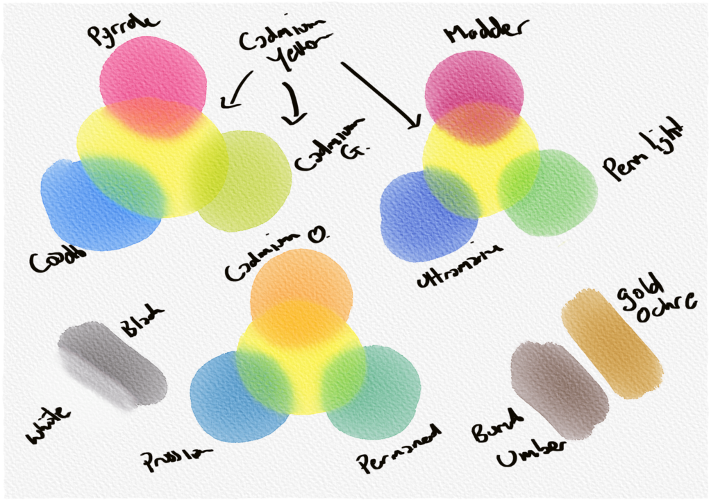
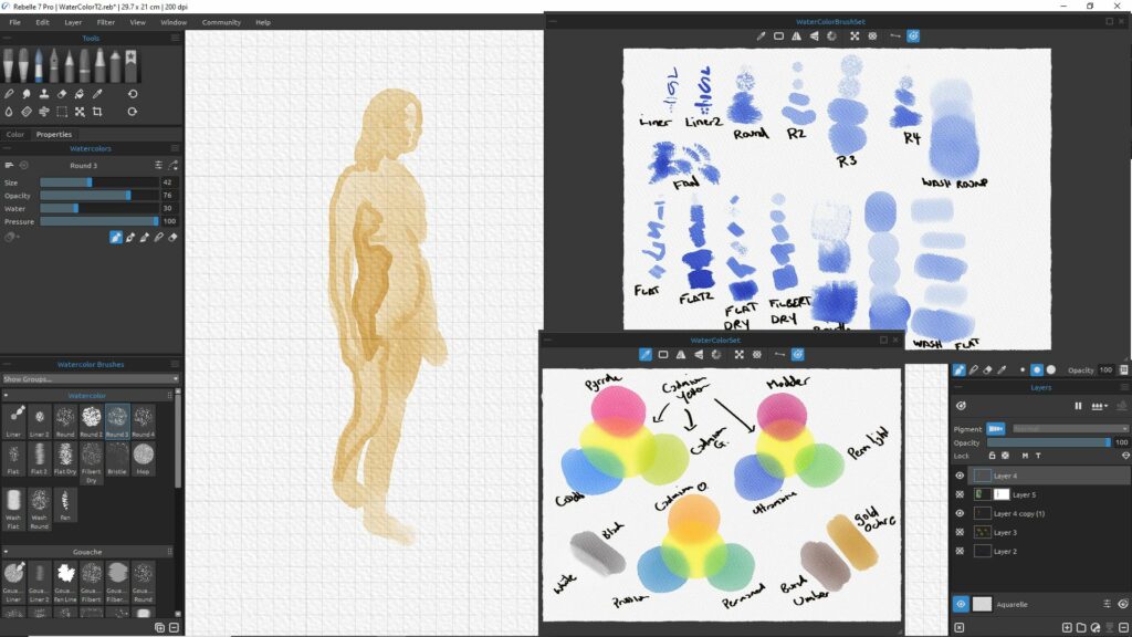
I worked out that if you do color pallets and brush tests then export them as an image file you can then import them as references to help with knowing the effect of a brush or a color mix. This has been pretty useful for finding the right tools for the job and also for exploring how Rebelle 7 mixes it’s color and mimics real media (especially for the Watercolor tools and the wet paper feature).
It’s very similar to what I would do with real media so seemed a natural step. I will probably end up doing dozens of these into an archive for future painting. It’s also really handy for color picking as you can set up a palette and just use the dropper tool to pick up colors directly from the reference image.
Rebelle 7 – Default Watercolor Brush SetWater Color Pallete – Testing Color MixesUsing them as a reference image while working
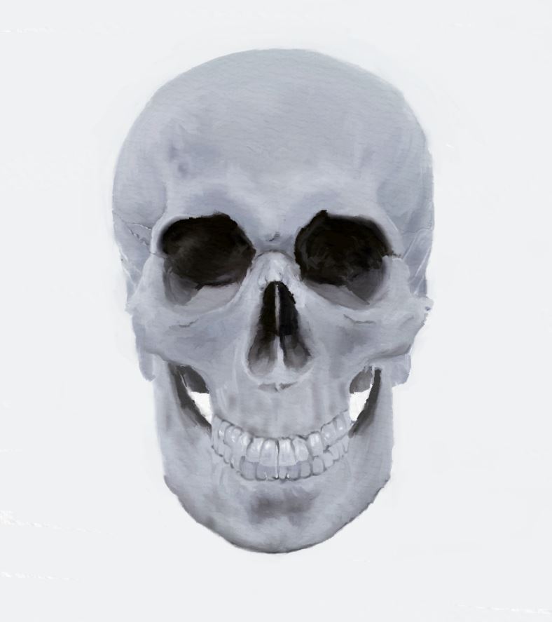
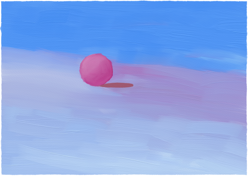
My first real go with Rebelle 7 on a semi-serious study.
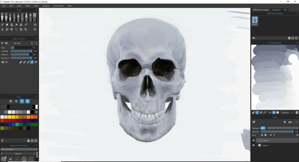
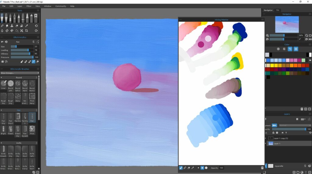
I’m finding the flat oil brush to be the most useful. Especially when set to blend. It’s kind of like sculpture the way it lets you move the paint around to make forms. It’s really is like using real oil paint – except that it never dries out and you can work it endlessly over a week. I did the background with an oily knife brush which was very pleasing and surprisingly like using a real pallet knife. I tried the airbrush but was not that happy with the result (I’m not really an airbrush aficionado) it just looked like a dirty patch but I’m probably not using it correctly. The use of an inbuilt reference window and guides that could be replicated onto the work is a really nice feature as well. Still the killer feature for me is being able to mix paint into tones on the pallet mixer. The UI and the Windowing system is a little clunky with windows and side bars sometimes falling off the screen and resetting when the application is minimized (on a Windows 10 machine) but I’m learning to look past those quirks.
Very much enjoying playing with Rebelle 7 Digital Painting software. I started with a basic ball study and the oil brushes. I love having a texture and grain to work against. This is very much like painting with real paint. Not missing the smell of turps.
Most of the work was done with a simple flat brush and lots of playing with the mixing palete. This is probably the killer feature for me – being able to mix colors and tones and gradient shades myself.
There has been a bit of a learning curve and some of the windowing features are a bit clunky but it’s a totally enjoyable experience to paint with and made me excited to work again. I cannot wait to get into the Watercolor set.
Stuff that I learned from the Godot Step-by-Step starter tutorials. I’m hoping I can shorten someone else’s journey (plus this is how I document stuff).
A Godot Game is a tree of Scenes (*.tscn files from the project explorer) and Scenes are made up of Nodes (the primitive types in a Godot game).
In the 2D starter tutorial we made four scenes:
Main.tscn
Player.tscn
Mob.tscn
HUD.tscn
You can see from the list of scenes (below) that the logical grouping of a Main controller scene – a Player and a Mob (Bad Guys) scene and the HUD scene is split out. The Main scene is the starting point for a Godot game. Scenes can be instantiated (many times as objects within another Scene – and edited independently – or all objects can be changed globally by editing the *.tscn) .
As you can see above – each Scene had a related Godot Script file (*.gd) that holds the code for that Scene (more on that later).
Scenes are your basic building block and design element. For each component in the game – make a Scene.
Nodes have Properties and can receive callbacks to update every frame. They can be extended with new properties (and functions). They can be nested under another node as a child (the tree structure).
Properties can be edited in the Inspector Window to the Right of the Godot Editor. The Inspector displays a node’s properties in “Title Case” which are available to GDScript code (As lowercase – with words separated by an underscore – hover over Properties in the editor to check them).
Example: a script on a 2D Sprite Character that starts with:
extends Sprite2D
Which grants access to all the inherited properties of a 2D Sprite visible in the Inspector – which means you can write:
var texture = load("res://icon.svg")
$Sprite2D.texture = texture
Doing Stuff
Game Window Size Settings
Click on Project -> Project Settings to open the project settings window and in the left column, open the Display Window tab. There, set “Viewport Width” to 480 and “Viewport Height” to 720.
Player Input
There are two main ways to process input :
The built-in input callbacks, mainly _unhandled_input(). Like _process(), is a built-in virtual function that is called every time there is a keypress. Use if if you need to react to events that don’t happen every frame (like hitting Space to jump). To learn more about input callbacks, see Using InputEvent.
The Input singleton. A singleton is a globally accessible object. Godot provides access to several in scripts. It’s the right tool to check for input every frame.
We use the Input singleton here as we need to know if the player wants to turn or move every frame.
Managing input is usually complex, no matter the OS or platform. To ease this a little, a special built-in type is provided, InputEvent. This datatype can be configured to contain several types of input events. Input events travel through the engine and can be received in multiple locations, depending on the purpose.
Here is a quick example, closing your game if the escape key is hit:
func _unhandled_input(event):
    if event is InputEventKey:
        if event.pressed and event.keycode == KEY_ESCAPE:
            get_tree().quit()
However, it is cleaner and more flexible to use the provided InputMap feature, which allows you to define input actions and assign them different keys. This way, you can define multiple keys for the same action (e.g. the keyboard escape key and the start button on a gamepad). You can then more easily change this mapping in the project settings without updating your code, and even build a key mapping feature on top of it to allow your game to change the key mapping at runtime!
You can set up your InputMap under Project > Project Settings > Input Map and then use those actions like this:
func _process(delta):
    if Input.is_action_pressed("ui_right"):
        # Move right.
Animations
Adding animations to 2D Animation Node is a little non-obvious.
To create one, find the Sprite Frames property under the Animation tab in the Inspector and click “[empty]” -> “New SpriteFrames”. Click again to open the “SpriteFrames” panel: (Note that there are two tabs sitting next to each other there in the panel – both called Sprite Frames – which is kind of like an expanded info box for the first Sprite Frames tab – doesn’t look obvious but it is when you know it’s there).
On the left is a list of animations. Click the “default” one and rename it to “up”.
The Animation Sprite Pane is called “Sprite Frames” down the bottom (in blue) – (it’s easy to lose it if you click on something else and then go looking for it in the obvious Animation footer): Add sprites by clicking on the little “folder” icon (next to the play/pause strip).
Anti-Aliasing
I was a bit disappointed with how scenes looked when I started playing with my own demo scenes but once I found the Anti-Aliasing settings I got more comfortable. Under Project -> Project Settings.
The difference between this:
and this:
GDScript
GDScript is an indent-based language – which is really annoying. I make tabs and spaces by muscle memory all the time when coding and it bites me in the ass. Cutting and Pasting code is also fraught with danger. But annoyances aside I do really like it as a scripting language – it’s simple, well designed (in that interfaces are consistent and logical) and does what you want with a minimum of fuss.
The only other gripe is that there are a lot of setting strings for references in the editor so you need to be careful when using them in code that you spell them correctly and are aware that they are case sensitive. For example you may have set an animation called “funnyWalk1” in the editor so when you code it in GDScript you need to use something like below:
if velocity.x != 0:
    $AnimatedSprite2D.animation = "funnyWalk1"
It would be nice if there was some kind of style checker or linter that could roll over your code for strings and do a fuzzy match against the instances in the editor and tell you when you used FunnyWalk1 or funnywalk1 or funnywolk1 or funmyWalk1 etc.
Inspector Access
Using the export keyword on the first variable speedallows us to set its value in the Inspector
@export var speed = 400 # How fast the player will move (pixels/sec).
Here, rotation is a property inherited from the class Node2D, which Sprite2D extends. It controls the rotation of our node and works with radians.
The func keyword defines a new function. After it, we have to write the function’s name and arguments it takes in parentheses. A colon ends the definition, and the indented blocks that follow are the function’s content or instructions.
Note: Notice how _process(), like _init(), starts with a leading underscore. These are Godot’s built-in functions you can override to communicate with the engine.
_process()is called every frame (it’s the equivalent of Update() in Unity).
Godot 4.0: nonexistent function “instance” in base PackedScene Instance is Godot 3, on 4 is instantiate()
PathFollow, offset (the path length moved from the beginning in distance units). PathFollow2D, you’ll see that it no longer has offset as an attribute – the new name is “progress”.
V3 has linear_interpolation in V4 it has been replaced with lerp.
I don’t often get excited about software (OK I got a little bit excited about the more recent Blender updates to the animation suite) but today is the release day of Rebelle 7. I’ve been a serial tester of graphics programs and Rebelle Painter has been on my wish list for some time. I’ve literally been hanging out for months like a kid the night before Christmas. (Yeah I did justify the purchase as a gift to myself).
The mix of digital and ‘native’ painting is just what I’ve been missing in my workflow. I love my analogue art making process. For someone who spends all day in front of the screen nothing is better than having real paint to mix or flowing ink and watercolor. Rebelle crosses this boundary and allows me to take the workflow of my traditional painting and use it in my digital art. This is especially important for me. Making games is an art for me – and coming from a fine arts background I really want to inject that into it. No matter how awkward that fit that sometimes is.
I’ve had almost two years off delivering a game with returning to full time work at the Xiabatsu and with the heavy lockdown in Melbourne. But it really gave me a chance to get into oil painting and spend months mixing and painting color patches. I’ve been a ClipStudio convert for some time and it does a semi-decent watercolor effect but that’s really all it is. Being able to mix colors and work with wet or dry paper on Rebelle is simply awe inspiring.
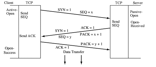
This is an embarrassing post. Some days are there to simply remind you that you don’t really know what you are doing. I spent two days trying to track down why my networking scripts were not working when I ran them in the editor. Turns out that the editor makes it’s own internal network stack when running a project which does not connect to the normal ethernet ports on your machine.
Top Tip ! Build you project and run it natively if you are using TCP/IP connections ! Don’t try and run it in the editor (not even for quick checks or small simple projects) it simply won’t work.
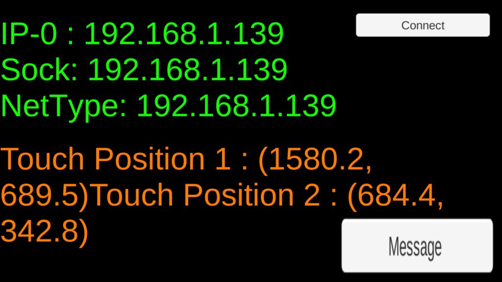
The really nice thing is after I got it all working I built a touch screen controller for Android phones that can be used as input in a Unity game.
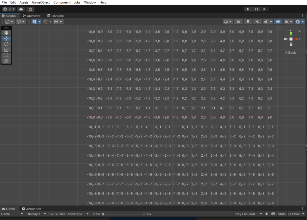
I’ve been working with the FFTWindow analysing audio input and needed a quick way to view the coordinate space of the grid. I’m surprised there is not a feature in Unity to do this (at least not that I could find). This is a quick script to help with debugging coordinates in the Scene View.
Grid Line Coordinates on the XY plane
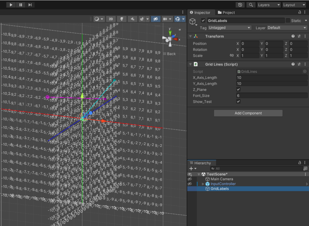
The script basically just draws a set of Axis in the scene and labels the x,y,z coordinates. It’s best when you are viewing along the alignment of an axis (I use the XYZ Gizmo in the corner to switch between them).
In 3D view with Cyan and Magenta sample lines.
You can toggle the Z plane on and off to make it easier to see just the XY plane and there is a few sample lines to show how it might be useful.
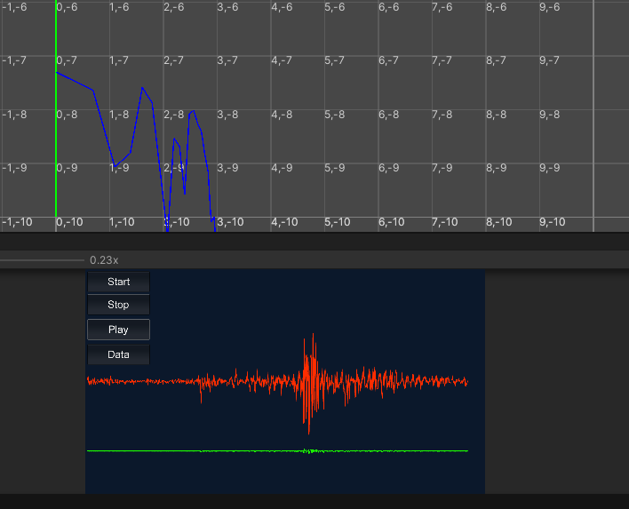
I was using to analyse audio spectrum data on the fly like this:
The blue Logarithmic representation of the PCM signal in red
Code
Here is the code for the grid lines/coordinates below:
using System.Collections;
using System.Collections.Generic;
using UnityEngine;
using UnityEditor;

public class GridLines : MonoBehaviour
{
	public int X_Axis_Length = 10;
	public int Y_Axis_Length = 10;
	public bool Z_Plane = true;
	public int font_Size;
	public bool show_Test = true;

	private GUIStyle guiStyle = new GUIStyle(); //create a new variable
	public void OnDrawGizmos()
	{
		// Axis
		Gizmos.color = Color.red; // X
		Gizmos.DrawLine(new Vector3((X_Axis_Length / -1), 0, 0), new Vector3((X_Axis_Length), 0, 0));
		Gizmos.color = Color.green; // Y
		Gizmos.DrawLine(new Vector3(0, (Y_Axis_Length / -1), 0), new Vector3(0, (Y_Axis_Length), 0));
		Gizmos.color = Color.blue; // Y
		Gizmos.DrawLine(new Vector3(0, 0, (X_Axis_Length / -1)), new Vector3(0, 0, (X_Axis_Length)));  // assumes Z Axis is the same length as the X


		//Gizmos.DrawWireSphere(centre, Radius);
		guiStyle.fontSize = font_Size;
		int x = -X_Axis_Length;
		int y = -Y_Axis_Length;

		while (x < X_Axis_Length)
		{

			Handles.Label(new Vector3(x, y, 0), (x + "," + y));

			while ( y < Y_Axis_Length)
			{
				Handles.Label(new Vector3(x, y, 0), (x + "," + y));
				y++;
			}
			 x++;
			 y = -Y_Axis_Length;
		}

		if (Z_Plane)
		{
			int z = -X_Axis_Length;	// Z Axis
			y = -Y_Axis_Length;

			while (z < X_Axis_Length)  // Z Axis
			{

				Handles.Label(new Vector3(0, y, z), (z + "," + y));

				while ( y < Y_Axis_Length)
				{
					Handles.Label(new Vector3(0, y, z), (z + "," + y));
					y++;
				}
				z++;
				y = -Y_Axis_Length;
			}
		}

		if (show_Test)
		{
		// Test lines
		Gizmos.color = Color.cyan;
		Gizmos.DrawLine(Vector3.zero, new Vector3(4, 5, 0));
		Gizmos.DrawWireSphere(Vector3.zero, 0.2f);
		Gizmos.DrawCube(new Vector3(4, 5, 0), new Vector3(0.2f, 0.2f, 0.2f));

		Gizmos.color = Color.magenta;
		Gizmos.DrawLine(new Vector3(-3, 3, -3), new Vector3(2, 2, 2));
		Gizmos.DrawWireSphere(new Vector3(-3, 3, -3), 0.2f);
		Gizmos.DrawCube(new Vector3(2, 2, 2), new Vector3(0.2f, 0.2f, 0.2f));
		}
	}
}
Quick Tip: I have been working on a TCP/IP Networking project using a client/server architecture. The client (and the server for that matter) are both relatively small code bases and the UI and object count are really low in the scene. I had been struggling with CPU load in the project and feverishly trying to work out why my code was baking the CPU (and GPU!). I’d assumed it was something stupid I had done in a loop with the networking structures I was not that familiar with. It’s really not easy to concentrate on new code when your laptop fan is literally screaming at you! I’d hit Play and the CPU would spike almost immediately. So I would switch to my local terminal and scrape through the open ports and network connections looking for a smoking gun. Turns out it was the default frame rate in the Editor trying to deliver the fastest graphics performance it could on my PC – and with such a low object count and and very simple graphics being asked for it was running like a Formula One race car when all I wanted was an old jalopy.
This is my CPU on Speed
Solution: Set Target Frame Rate!
A Unity project will attempt to run your project as fast as possible. Frames will be rendered as quickly as they can (limited by your display device’s refresh rate).
There are two ways to control frame rate:
Application.targetFrameRate – controls the frame rate by specifying the number of frames your game tries to render per second. (I wrote a script to use this – see below).
QualitySettings.vSyncCount – specifies the number of screen refreshes to allow between frames. (look for it in the Editor Settings). For a 60Hz display, setting vSyncCount=2 will cause Unity to render at 30fps in sync with the display.
Note that mobile platforms ignore QualitySettings.vSyncCount and use Application.targetFrameRate to control the frame rate.
The default value of Application.targetFrameRate is -1. (the platform’s default target frame rate)
I set mine using the script to 20 and when I hit Play got this result:
This is my CPU chilling out
using UnityEngine;

public class SetFrameRate : MonoBehaviour
{
		[SerializeField]	// Just so you can check it in the inspector
		private int FrameRate = 20; // 20 is really low but got my CPU down to < 10% - 30 is the target for mobile and was < 20% CPU usage
		//private int FrameRate = -1; // reset to default

		private void Awake()
		{
			Application.targetFrameRate = FrameRate;
		}
}
I attached it to my Camera object.
Set Frame Rate
One interesting behavior of setting this using a script in Unity 2020.3.26f1 was that once it was attached to the Camera object and Play was initiated for the first time it must have set the frame rate somewhere internally in the Engine. When I removed the script (for testing) the frame rate did not automatically reset to -1. I had to re-attach the script and update it to set the frame rate back to the default. I had a search of the settings in the Inspector and Preferences and couldn’t find a visible reference to it anywhere so you have to be careful if you are going to put this on a Production build that you reset it before releasing otherwise you might end up with a lower frame rate than what the platform could achieve by default.
Enough procrastination – back to sockets, ports and buffers.
I’m looking to see if there are any advantages to using Blender as a 2D Animation tool using meshes over Unity’s Spline Sprite based animation system. The differences between them at the effort and usability/flexibility layer are many and subtle. Hence the investigation. The two biggest differences for me is that 1. With the Blender animation option you are animating in Blender (which I like much more than animating in Unity). But the down side is that you have to import the animations into Unity and it’s pretty hard to modify once they are there. Which also means that it’s harder to adjust them to react to other actors, objects, and scene elements once you get it into the game. 2. With the Blender approach it’s a mesh in Unity not a Sprite so you can do all the transforms that mesh’s support. You can also light it as a mesh (the default Sprite Renderer cannot be lit). Being able to use light effects on a 2D image within the game is pretty huge for making it look pretty and making effects or plot devices (think lightning on a dark and stormy night). You can get light effects on Sprites in Unity if you swap out the default shader with another shared and with the Light Weight Render Pipeline in Unity (LWRP) but not every project will suit that. There are also Unity solutions that use custom shaders or use a similar mesh and material based solution (see further below for more on that).
Comparing Unity Sprites to Blender Meshes in Unity
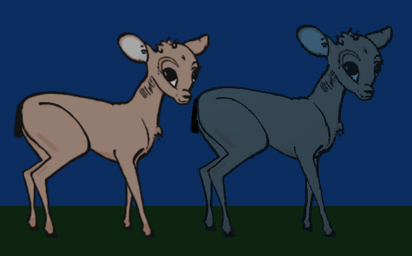
The images directly below are taken from the Game Screen in Unity. The one on the left is a Sprite based Spline rendering while the one on the right is the Mesh based fbx from Blender. You can see the difference in quality between the Sprite on the left and the lossy baked images of the Mesh on the right – it’s not huge and can be improved with some tweaking (Bilinear Filter mode and upping the Ansio Level to 2 helped with the anti-aliasing and working with the material Metallic and Smoothness parameters also helped).
Sprite (left) and Mesh (right)Night Time lighting affects the Blender mesh image but not the Sprite based image.Lighting effects can be much more complex and creatively arranged to hit separate parts of the mesh.
As stated above you can drop an image onto an object in Unity as a material but it doesn’t light as well and is prone to shadowing. Use the Cutout and not the Transparent Rendering Mode in Unity or you get this shadow on the transparency. The below image shows a material with a standard shader with an image on a Unity 2D plane mesh but there is a shaded square around the outside that marks the image boundary.
Transparency Shader
The image below is the same sprite using a material with a standard shader and a cutout rendering mode (the diffuse sprite shader worked similarly). The top one is a normal sprite renderer with the custom material replacing the default-sprite material. The bottom one is a Unity 2D Plane with the custom material applied. Both tests look better than the quality of the Blender imported model and could be layered and they react with lighting in game.
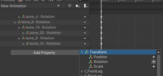
So these are the alternatives to the process I’m describing below with Blender and they are good and valid options. I guess the only reason why I would choose to use the Blender animation workflow is because I hate doing this process in Unity’s Animator window. Add Property | drill down through the object | the child | the other child | the bone | the transform | and finally the tiny little plus sign that let’s me add one manipulation point! For a Deer Kick I had 88 different animation points – that’s a LOT of stupid clicking down through an object hierarchy to add Properties (I know you can hold down shift and add more than one property at a time but you still have to manually expand them all). The other alternative is to right click and add all properties for an object and then if you are patient enough you can remove the one’s you don’t use.
I do like the record feature that adds properties dynamically but these problems and that I find the interface finicky and too small made me look at Blender.
Importing the Images to Blender and Setting up the Workspace
Moving on to working in Blender with images and Meshes the basic process is this:
For every layer in the artwork of our animated character we exported a separate image file on a transparency. Each png file is imported into Blender as an empty image object (Add | Empty | Image) you could use a reference or background image but since all the parts might move I wanted to group them all under empties.
A Mesh is created for each image and either shaped to the outline of the image or left as a plane and weighted correctly (more on that later).
The image is baked into the UV of the mesh.
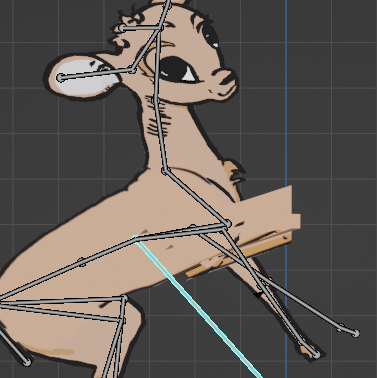
The components are then parented to an Armature with automatic weights.
The meshes are weight painted to correct the deforms.
Now it’s ready for animation.
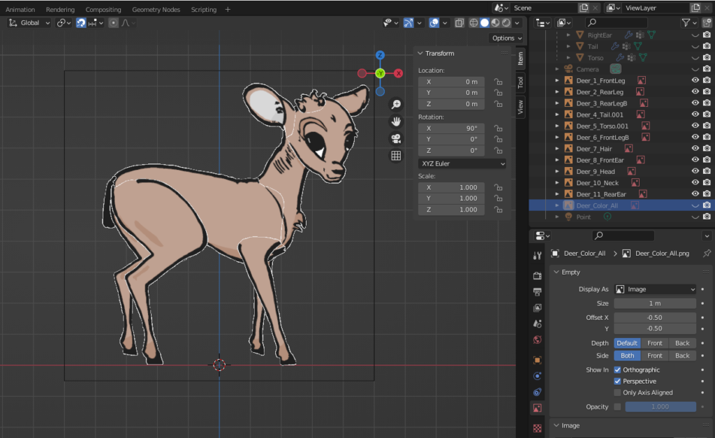
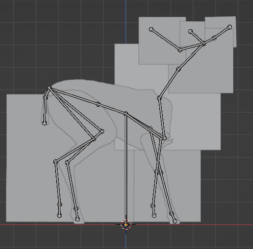
The image objects are all placed at the same origin (0, 0, 0) and rotated 90 degrees on the ‘x’ Axis so they are visible in the viewport from the “front” view.
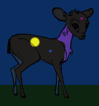
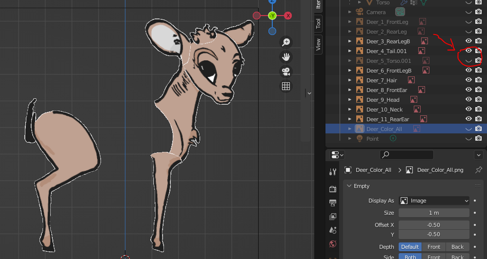
All the Deer components Frankenstein’d together into a whole The visibility of parts are toggled on and off so individual pieces can be worked on.
Making the Mesh’s
For each piece a mesh is made. I took two approaches here: 1. Model a plane mesh as closely as I could to the shape of the sprite. 1. Use a plain rectangular mesh and use weight painting to deform correctly.
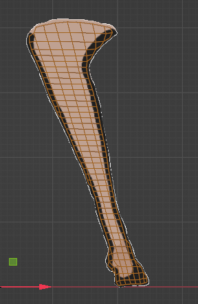
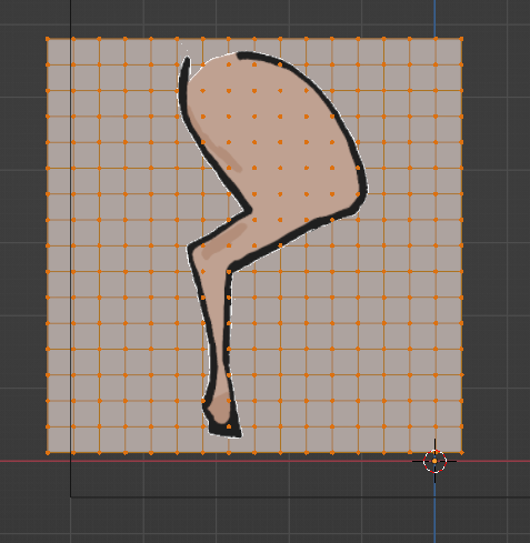
To start with the modelling approach I started with an image and dragged a plane in edit mode over it as a wireframe. The origin of the plane was kept at 0, 0, 0 so all the pieces that were made had a common reference (same as all the images). Using basic mesh deform and subdivision I created a mesh that matched the image.
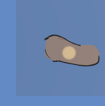
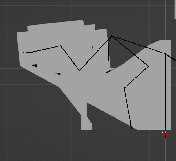
The foreleg Mesh
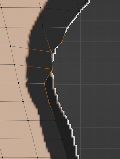
The method was a lot of work manually placing each vertex on the border of the image boundary. If the vertex is placed a little bit outside the image you get a white space on the final product and if you don’t come all the way to the edge you lose some of the black line and smooth finish (UV mapping is slightly out). Plus I found that if you have to warp the mesh too much for a sharp angle or awkward placing of the square tiling you get some minor defects along the line during animation.
Vertices placement
After about the fourth component I got a bit sick of manually moving around vertexes. So I took another approach of just using a rectangular mesh and relying on the transparency of the image to do all the work. This is much easier and faster but there were gotcha’s during adding the armature and weight painting. This rear leg below is just one big mesh subdivided into enough squares to give a decent deform without stretching or warping the black line during animation.
Venison
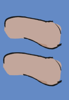
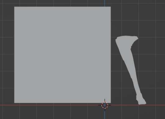
In Solid shading here is a comparison of the rear leg mesh and the front leg mesh.
Solid Mesh Planes
The image below is both meshes in Render mode (including the armature) and you really can’t tell the difference between them.
Rendered Meshes
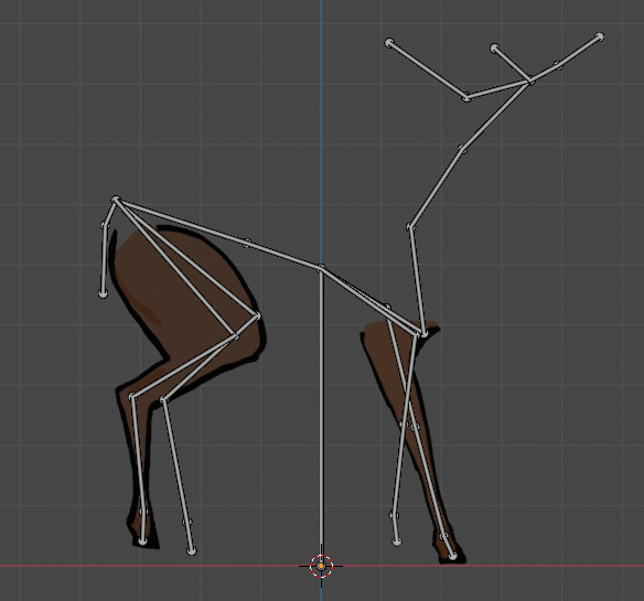
The whole mesh ended up looking like this:
Armature and Weight Painting
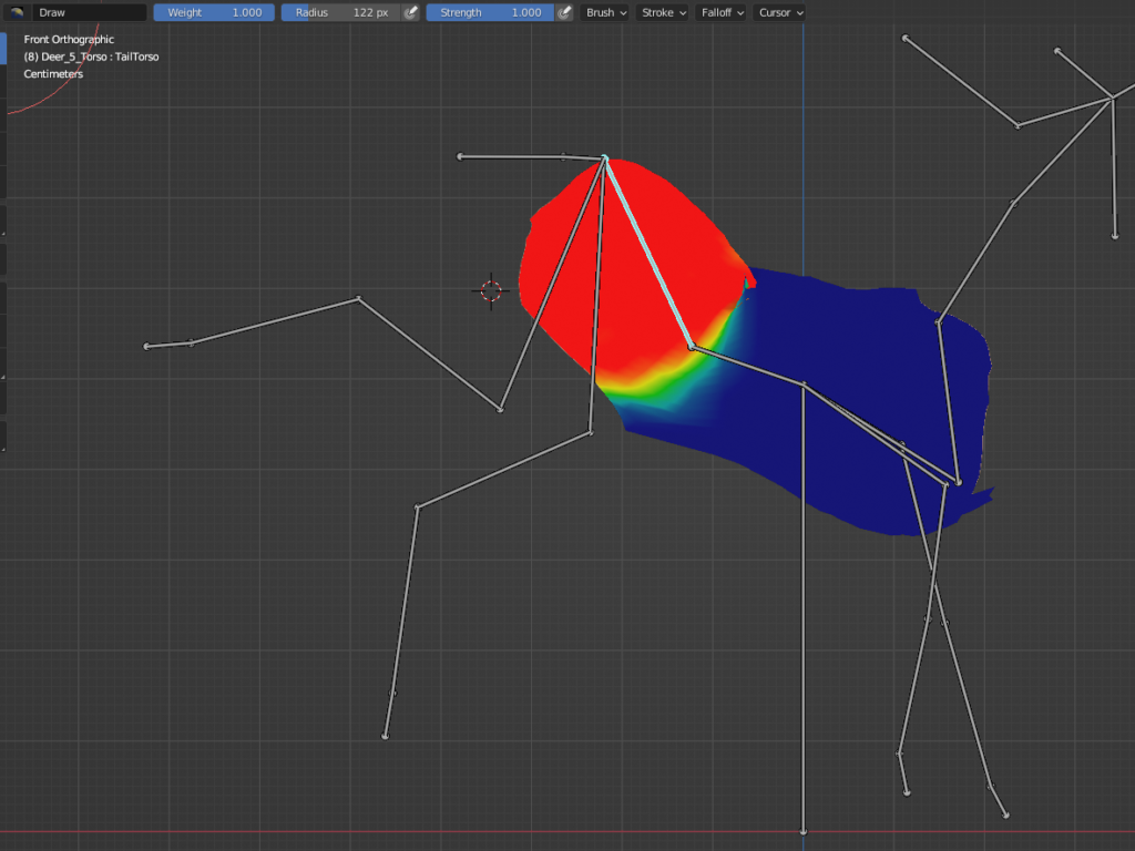
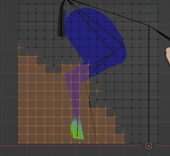
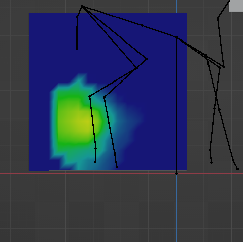
As you can see above the armature was added and the Mesh objects were parented to it with automatic wights. Because everything is a flat plane of which some are meant to overlap the others (like the closest front leg is in front of the torso and the back leg is behind it) parenting the armature with automatic weights meant that both front, middle, and rear mesh’s would get an equal measure of weight in parts. This all had to be manually painted.
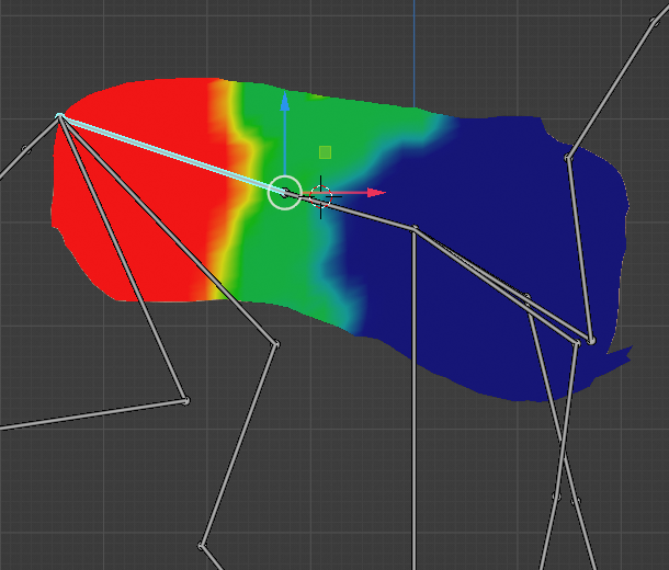
Here the Torso was weighted across three bones and only the rear was affecting the rump (any leg meshes had to be removed from these vertex groups).
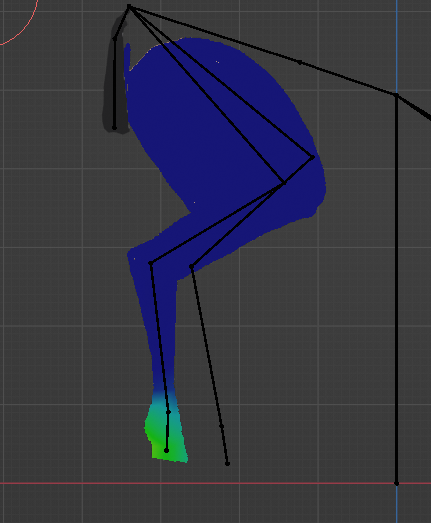
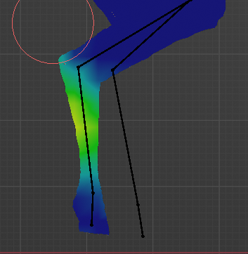
Weights had to be carefully graded otherwise warping of the line would result:
The weight is too strong a transition here.It causes artifacts like this.This is the resulting gradient changes in weight to get a correctly deforming line.
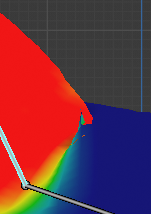
The other problem was that random single or lone groups of vertices would be weighted to a bone and not visible until you moved it in pose mode: A few vertices on the chest were registered to the root bone. These all have to be manually removed.
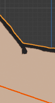
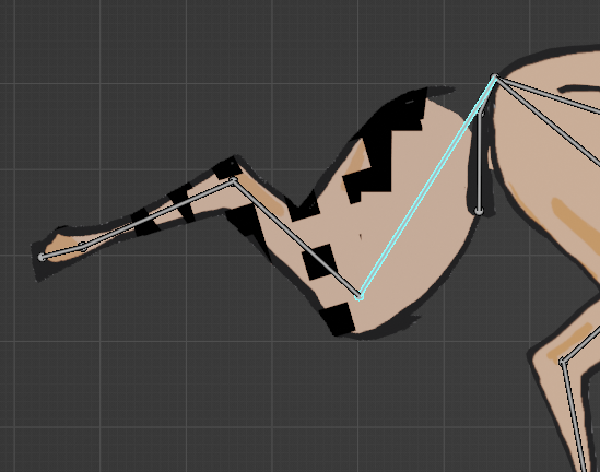
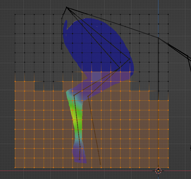
The other interesting anomaly with the large rectangular plane meshes was that the weight would sometimes cause improper warping of the mesh which bent it round itself in places and showed up as black squares.
The foot vertex group covers all these vertices.Which you cannot tell in edit mode when you select it with “show weights”. During transform in animation these black marks show where the mesh does not warp properly.The mesh is a mess.It’s because the shin bone weight doesn’t go all the way to the edge.It looks right in edit mode.But if you use the vertex group to select all the vertices it should look like this (all the way to the edge).
These are pretty quick things to fix really but it took a while to work out what exactly was happening. It’s was still faster than individually making all the mesh components by hand to fit the image.
Probably a better workflow would be to make reduced simpler meshes that fit closer to the image but don’t have to slavishly man handle the vertices around the borders.
The Shading
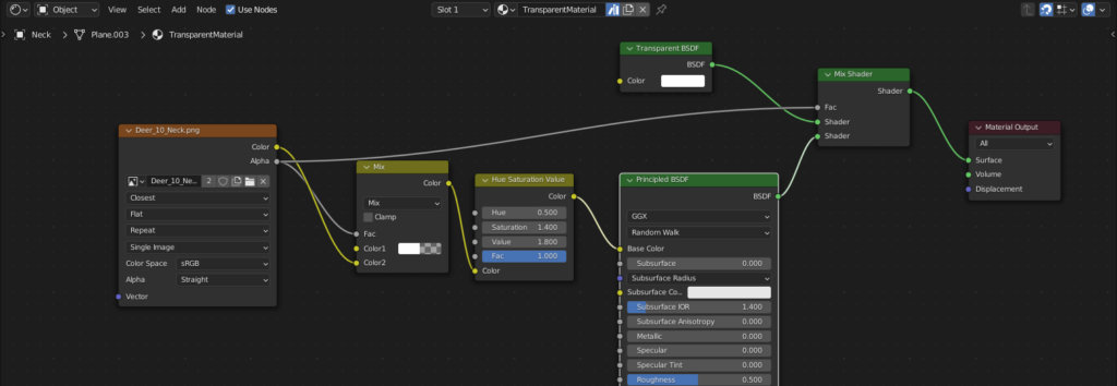
UV Mapping is totally easy here but getting the material right was a bit tricky with the transparencies and images. This is the setup I used:
9. Add new Materials and import the UV images into Unity.
10. Add the *.fbx imported asset into a scene.
11. Add an Animator Component and drag the animations from the prefab into it.
12. Set up Triggers and connections for the animations.
It’s a lot of work. Especially if you make a custom mesh for each piece of art. But I did all this as I really like animating in Blender (especially now that the Pose Library is functional and part of the Asset Browser). But to tell the truth I think I got better results using the Spline system in Unity 3D with much less work. There are trade offs and I’ll go through them below after more exposition on the workflow.
In this post I’ll go through the asset creation process in Clip Studio.
Making the Asset
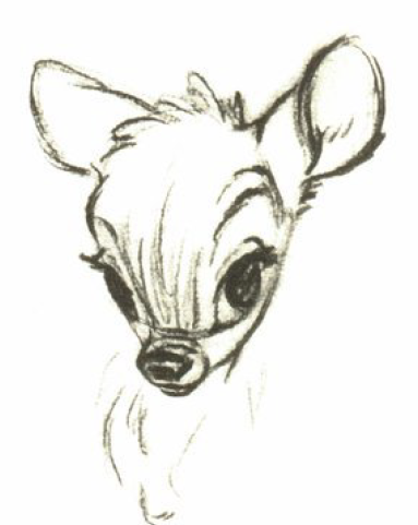
The 2D game has a bunch of cute animals so I dug deep into the Disney Sketchbook by Ken Shue and pulled out Bambi for inspiration.
An early Disney sketch
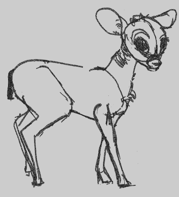
Using this as a rough guide I drafted a few basic shapes for a “Deer” character which looked like this:
Rough Sketch for the 2D Asset
I started using Clip Studio last year in place of the Gimp. I’ve tried all sorts of painting programs and would choose Gimp over most of them (I will not spring for a paid version of Photoshop – it’s extortion!) but Clip Studio won me over with it’s brushes. It’s not expensive by comparison and I really like how it fits into the specific things I want out of an art program. I’ll often go back to Gimp for projects that require a lot of filters and image manipulation but for straight drawing on the PC Clip Studio is a good fit for me. I like how you can make custom tools that mimic your real life counterparts for a pencil or brush and find this program better at it than most (though Adobe Sketchbook runs a close second).
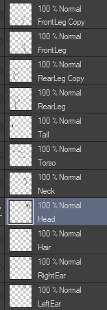
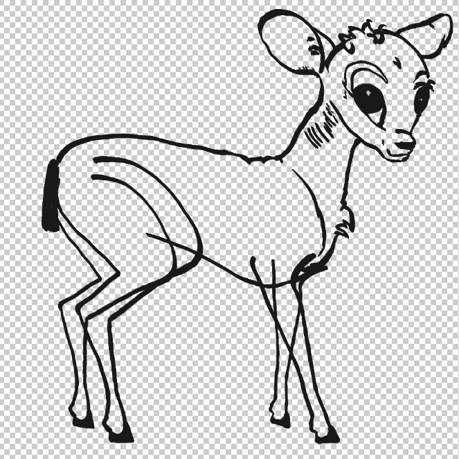
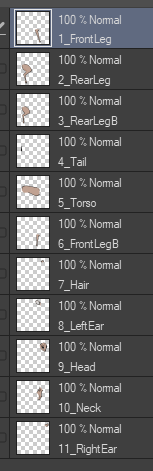
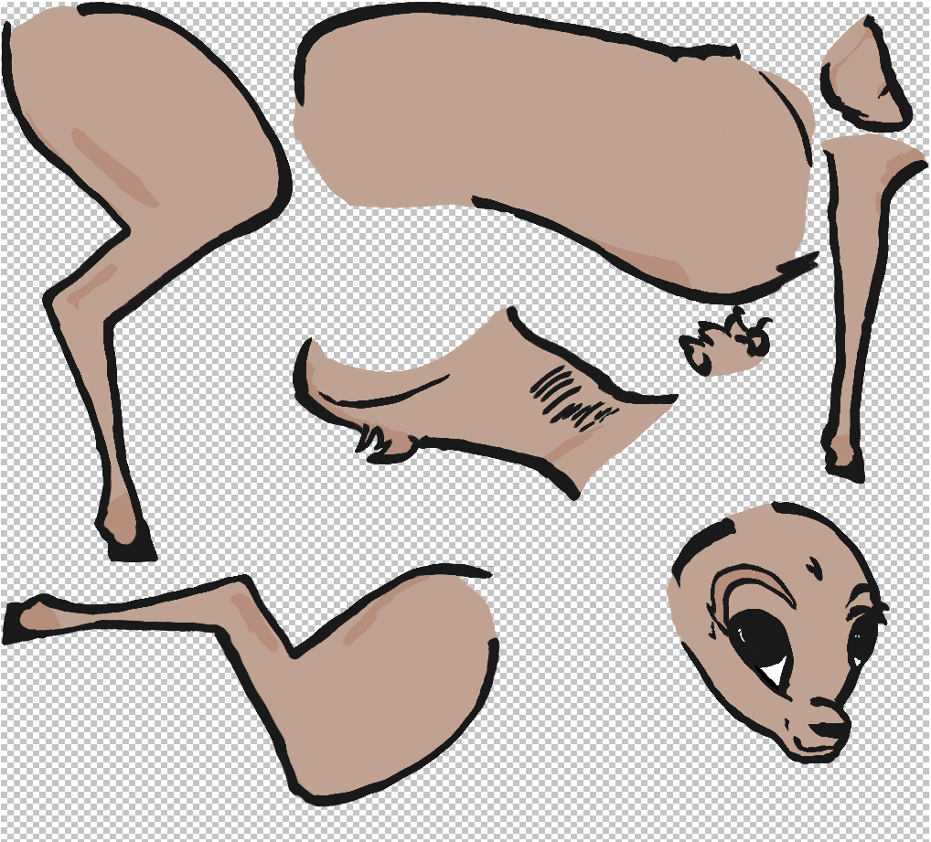
To start with I create a set of layers for the Inking of the artwork. One for each moving element in the final asset.
There is a pretty simple formula for this where each limb or piece gets a layer. But you have to have a general idea of what you are going to need in the final asset and what animation is required. There is no point doing a separate component if it’s not going to move or be seen in the final product. Trouble is a lot of this work is iterative and often you find that you have to go back and change something when it doesn’t look right. There needs to be an awareness of where pieces overlap and what lines are going to be warped by the armature bending or where a line needs to be extended behind a piece that might move and reveal where it ends by another layer.
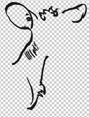
The Inking Layers This is how the inking layers sit on top of each other that shows where lines overlap or extend.
It’s really easy to see on the body and legs but even here on the pieces surrounding the head the lines that make up the ears and hair and neck all have to move independently but still look connected.
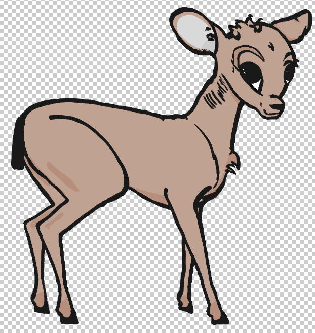
Once I’m done with the inking stage I add more layers for color. At this point the whole file gets saved as export copy and the layers are merged into one for each piece again and numbered in the order in which they will sit on the animation cell. I keep the older copy with the separate layers for everything and all the drafts so I can go back to it if I have to change something.This is the whole asset complete and ready for export. Each layer is exported individually as a *.png. The file size of each one is 1024 x 1024 pixels with 600 dpi and a transparent background.The *.png files are imported into the Texture Packer to minimize the material size in the final project. Each of these elements get’s UV mapped to a mesh in Blender but more of that later in the next post.
Start to finish this took a couple of days elapsed time as there is a lot of noodling about with formats, designs and what-not.
Next up I’ll go into the Blender workflow and preparing the art for animation with complex and simple meshes.